Electrical tester PCE-BDM 20
Digital multimeter for the stationary workplace / Various measurement functions / High measuring ranges / PASS / FAIL function for component testing / HOLD function / Connection of two thermocouples simultaneously / Software / USB interface
Digital multimeter for the stationary workplace / Various measurement functions / High measuring ranges / PASS / FAIL function for component testing / HOLD function / Connection of two thermocouples simultaneously / Software / USB interface
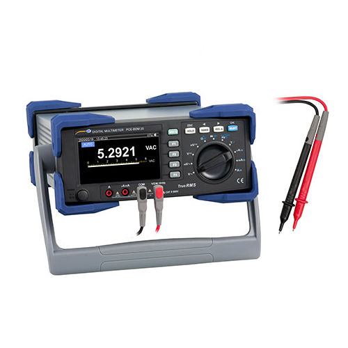
The digital multimeter is a multimeter for a stationary workplace. In addition to measuring current, voltage and resistance, the digital multimeter can also use two thermocouples to measure the temperature and also determine the conductivity. So the digital multimeter can perform a variety of different measurement tasks. A direct connection to a PC can be established via the USB interface on the back of the digital multimeter. The software from the digital multimeter can then be used to carry out live analyzes using graphics and tables.
Another special feature of the digital multimeter is the PASS / FAIL function. With this function, target ranges for the measured values can be set for each measuring function. Depending on the actual measured value, a “PASS” (passed) or a “FAIL” (failed) is then shown on the display by the digital multimeter. The digital multimeter is therefore used, for example, in quality control. With the help of the adjustable handle, the digital multimeter can be adjusted for ergonomic use by the operator. The handle of the digital multimeter can also be used to change the workplace. The housing of the digital multimeter has a rubberized edge protection, which prevents damage.
– Table multimeter with reinforced housing
– USB interface for PC connection
– PASS / FAIL function for quality control
– extensive measuring functions
– Relate the measured value
– Measured value with bar graph display
– USB interface for PC connection
– PASS / FAIL function for quality control
– extensive measuring functions
– Relate the measured value
– Measured value with bar graph display
| AC voltage | ||
| Measuring range | Resolution | Accuracy |
| 60 mV | 0.001 mV | ± (0.6% 60 digits) @ 45 Hz … 1 kHz |
| 600 mV | 0.01 mV | ± (0.3% 30 digits) @ 45 Hz … 1 kHz |
| 6V | 0.0001V | ± (0.3% 30 digits) @ 45 Hz … 1 kHz |
| 60V | 0.001V | ± (0.3% 30 digits) @ 45 Hz … 1 kHz |
| 600V | 0.01V | ± (0.4% 30 digits) @ 45 Hz … 1 kHz |
| 1000V | 0.1V | ± (0.6% 30 digits) @ 45 Hz … 1 kHz |
| Input impedance:> 10MΩ | ||
| Surge protection: 1000V | ||
| Display: True RMS in the measuring range of 10 … 100% of the respective measuring range | ||
| DC voltage | ||
| Measuring range | Resolution | Accuracy |
| 60 mV | 0.001 mV | ± (0.025% + 20 digits) |
| 600 mV | 0.01 mV | ± (0.025% + 5 digits) |
| 6V | 0.0001V | ± (0.025% + 5 digits) |
| 60V | 0.001V | ± (0.025% + 5 digits) |
| 600V | 0.01V | ± (0.003% + 5 digits) |
| 1000V | 0.1V | ± (0.003% + 5 digits) |
| Input impedance:> 10MΩ | ||
| Surge protection: 1000V | ||
| AC voltage + DC voltage | ||
| Measuring range | Resolution | Accuracy |
| 60 mV | 0.001 mV | ± (1% + 80 digits) @ 50 Hz … 1 kHz |
| 600 mV | 0.01 mV | ± (1% + 80 digits) @ 50 Hz … 1 kHz |
| 6V | 0.0001V | ± (1% + 80 digits) @ 50 Hz … 1 kHz |
| 60V | 0.001V | ± (1% + 80 digits) @ 50 Hz … 1 kHz |
| 600V | 0.01V | ± (1% + 80 digits) @ 50 Hz … 1 kHz |
| 1000V | 0.1V | ± (1.2% + 80 digits) @ 50 Hz … 1 kHz |
| Input impedance:> 10MΩ | ||
| Surge protection: 1000V | ||
| Display: True RMS in the measuring range of 10 … 100% of the respective measuring range | ||
| Alternating current | ||
| Measuring range | Resolution | Accuracy |
| 600 µA | 0.01 µA | ± (0.6% + 40 digits) @ 45 Hz … 1 kHz |
| 6000 µA | 0.1 µA | ± (0.6% + 20 digits) @ 45 Hz … 1 kHz |
| 60-mA | 0.001-mA | ± (0.6% + 40 digits) @ 45 Hz … 1 kHz |
| 600-mA | 0.01-mA | ± (0.6% + 20 digits) @ 45 Hz … 1 kHz |
| 10 A | 0.001 A | ± (1% + 20 digits) @ 45 Hz … 1 kHz |
| Display: True RMS in the measuring range of 10 … 100% of the respective measuring range | ||
| Overload protection: µA and mA Measurement: Fuse F 0.6 A 1000V Ø6 x 32 mm | ||
| 10 A measurement: F 11 A 1000V Ø 10 x 38 mm | ||
| When measuring almost 20 A, the measurement time should not be longer than 30 seconds. | ||
| After the measurement, the measuring device must rest for approx. 10 minutes. | ||
| Direct current | ||
| Measuring range | Resolution | Accuracy |
| 600 µA | 0.01 µA | ± (0.8% + 20 digits) |
| 6000 µA | 0.1 µA | ± (0.8% + 10 digits) |
| 60-mA | 0.001-mA | ± (0.8% + 20 digits) |
| 600-mA | 0.01-mA | ± (0.15% + 10 digits) |
| 10 A | 0.001 A | ± (0.5% + 10 digits) |
| Overload protection: µA and mA Measurement: Fuse F 0.6 A 1000V Ø6 x 32 mm | ||
| 10 A measurement: F 11 A 1000V Ø10 x 38 mm | ||
| A measurement of almost 20 A should not take longer than 30 seconds. | ||
| After the measurement, the measuring device must rest for approx. 10 minutes. | ||
| AC + DC | ||
| Measuring range | Resolution | Accuracy |
| 600 µA | 0.01 µA | ± (0.8% + 40 digits) @ 50 Hz … 1 kHz |
| 6000 µA | 0.1 µA | ± (0.8% + 20 digits) @ 50 Hz … 1 kHz |
| 60-mA | 0.001-mA | ± (0.8% + 40 digits) @ 50 Hz … 1 kHz |
| 600-mA | 0.01-mA | ± (0.8% + 20 digits) @ 50 Hz … 1 kHz |
| 10 A | 0.001 A | ± (1.2% + 20 digits) @ 50 Hz … 1 kHz |
| Display: True RMS in the measuring range of 10 … 100% of the respective measuring range | ||
| Overload protection: µA and mA Measurement: Fuse F 0.6 A 1000V Ø6 x 32 mm | ||
| 10 A measurement: F 11 A 1000V Ø10 x 38 mm | ||
| A measurement of almost 20 A should not take longer than 30 seconds. | ||
| After the measurement, the measuring device must rest for approx. 10 minutes. | ||
| Resistance | ||
| Measuring range | Resolution | Accuracy |
| 600 Ω | 0.01Ω | In REL mode: ± (0.05% + 10 digits) |
| 6 kΩ | 0.0001 kΩ | ± (0.05% + 2 digits) |
| 60 kΩ | 0.001 kΩ | ± (0.05% + 2 digits) |
| 600 kΩ | 0.01 kΩ | ± (0.05% + 2 digits) |
| 6 MΩ | 0.0001 MΩ | ± (0.3% + 10 digits) |
| 60 MΩ | 0.001 MΩ | ± (2% +10 digits) |
| Surge protection: 1000 V | ||
| With a measuring range of 60 MΩ the ambient humidity should be < 50%. | ||
| Conductivity | ||
| Measuring range | Resolution | Accuracy |
| 60 nS | 0.01 nS | ± (2% + 10 digits) |
| Surge protection: 1000V | ||
| The ambient humidity for the measuring range should be < 50%. | ||
| Capacity measurement | ||
| Measuring range | Resolution | Accuracy |
| 6 nF | 0.001 nF | ± (3% + 10 digits) |
| 60 nF | 0.01 nF | ± (2.5% + 5 digits) |
| 600 nF | 0.1 nF | ± (2% + 5 digits) |
| 6 μF | 0.001 μF | ± (2% + 5 digits) |
| 60 μF | 0.01 μF | ± (2% + 5 digits) |
| 600 μF | 0.1 μF | ± (2% + 5 digits) |
| 6 mF | 1 μF | ± (5% + 5 digits) |
| 60 mF | 10 μF | for reference only |
| Surge protection: 1000 V | ||
| Temperature | ||
| Measuring range | Resolution | Accuracy |
| -40 … 40°C | 1°C | ± (2.0% + 30 digits) |
| 40 … 400°C | 1°C | ± (1.0% + 30 digits) |
| 100 … 1000°C | 1°C | ± 2.5% |
| -40 … 104°F | 1.8°F | ± (2.5% + 50 digits) |
| 104 … 752°F | 1.8°F | ± (1.5% + 50 digits) |
| 752 … 1832°F | 1.8°F | ± 2.5% |
| Surge protection: 1000V | ||
| Two-channel temperature measurement | ||
| Temperature sensor: Type K only applies to the measurement of temperatures below 230°C / 446°F | ||
| Frequency measurement | ||
| Measuring range | Resolution | Accuracy |
| 60 Hz | 0.001 Hz | ± (0.02% + 8 digits) |
| 600 Hz | 0.01 Hz | ± (0.01% + 5 digits) |
| 6 kHz | 0.0001 kHz | ± (0.01% + 5 digits) |
| 60 kHz | 0.00 1kHz | ± (0.01% + 5 digits) |
| 600 kHz | 0.01 kHz | ± (0.01% + 5 digits) |
| 6 MHz | 0.0001 MHz | ± (0.01% + 5 digits) |
| 60 MHz | 0.00 1MHz | ± (0.01% + 5 digits) |
| Surge protection: 1000V | ||
| Input amplitude: 10 Hz … 30 MHz: 600 mV <a <30 Vrm,> 30 MHz: not specified | ||
| Duty cycle | ||
| Measuring range | Resolution | Accuracy |
| 10 … 90% @ | 0.01% | ± (1.2% + 30 digits) |
| (10Hz … 2kHz) | ||
| Surge protection: 1000V | ||
| Rise time: <1 µs, the signal is centered on the trigger level | ||
| Pulse width | ||
| Measuring range | Resolution | Accuracy |
| 250 mS | 0.001 … 0.1 mS | ± (1.2% + 30 digits) |
| Surge protection: 1000V | ||
| Rise time: < 1 µs, the signal is centered on the trigger level | ||
| 10 Hz … 200 kHz: pulse width > 2 µs | ||
| The pulse range is limited by the frequency of the signal | ||
| Continuity test | ||
| Resolution | Functional description | |
| 0.01 Ω | Short circuit alarm: from < 10 Ω, alarm switches off from > 50 Ω | |
| Surge protection: 1000V | ||
| Diode test | ||
| 0.0001V | The open circuit voltage is approx. 3V and the measurable voltage drop | |
| of the PN transition is < 3V A continuous beep | ||
| indicates the short circuit of the PN junction. The typical tension | ||
| of the silicon PN junction is between 0.5 … 0.8V. | ||
| Surge protection: 1000V | ||
| Further specifications on accuracy can be found in the operating instructions | ||
| Further specification | ||
| Interface | USB interface | |
| Supply voltage | 100 … 240V adjustable | |
| Environmental conditions � | 23°C / 73.4°F ± 5°C / 41°F, < 75% RH | |
| Dimensions | 310 x 240 x 120 mm / 12.2 x 9.4 x 4.7 in | |
| Weight | Approx. 3713 g / 8.2 lbs | |
เฉพาะลูกค้าที่เข้าสู่ระบบ และเคยซื้อสินค้าชิ้นนี้แล้วเท่านั้น ที่เขียนบทวิจารณ์ได้
สินค้าที่เกี่ยวข้อง
Electrical Tester
PCE-DC2
Electrical Tester
PCE-DM 15
Electrical Tester
PCE-LCT 1
Electrical Tester
PCE-ODM 12
Electrical Tester
PCE-CBA 20
Electrical Tester
PCE-HDM 7
Electrical Tester
PCE-AMM 5
Electrical Tester
PCE-HDM 5


รีวิว
ยังไม่มีบทวิจารณ์