

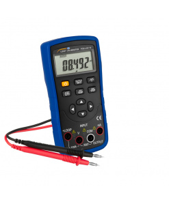
Current Calibrator PCE-RTD 20
PCE-RTD 20
Availability : กรุณาติดต่อสอบถาม
PCE-RTD 20 RTD Current calibrator
Simulation and Measurement of Resistance & Pt Sensors, Current and Voltage / Li-Ion Battery / Continuity Checker / Ramp Function
Simulation and Measurement of Resistance & Pt Sensors, Current and Voltage / Li-Ion Battery / Continuity Checker / Ramp Function
The RTD current calibrator PCE-RTD 20 is used to simulate resistors and resistance temperature sensors. Thus, the RTD current calibrator is able to be used as a calibrator for temperature measuring devices. In addition to the simulation of resistors, the RTD current calibrator has a measuring function for voltage, current and resistance. Both functions work independently. Furthermore, both connections are galvanically separated from each other.
The RTD current calibrator has many different characteristics for RTD sensors, so that a perfect calibration of thermometers of various kinds is possible. The RTD current calibrator has an accuracy of 0.02% in all measurement ranges and measurement functions. In addition to the direct specification of temperatures or resistances, the RTD current calibrator can be operated in ramp mode. Here, the user can decide whether the ramp should be run indefinitely or at defined intervals.
The PCE-RTD 20 RTD current calibrator is equipped with a mini-USB interface. This jack can be used to load the RTD current calibrator. Furthermore, recorded data can be transmitted via this interface.
– Simulation and measurement mode
– Battery operation
– Graphic LCD
– 24V supply for current loops
– HART compatible
– Manual mode & ramp function
– Continuity test
– Data logger function
– Battery operation
– Graphic LCD
– 24V supply for current loops
– HART compatible
– Manual mode & ramp function
– Continuity test
– Data logger function
| Measuring range | Resolution | Accuracy (of rdg.) |
| Measuring parameter voltage DC V | ||
| 0 … 30V | 0.001V | ± 0.02%of rdg. + 2 Dgt |
| Measuring parameter current DC mA | ||
| 0 … 24-mA | 0.001-mA | ± 0.02%of rdg. + 2 Dgt |
| Measurement parameter resistance | ||
| 0 … 400 Ω | 0.01 Ω | ± 0.02%of rdg. + 0.01Ω |
| Pt10 … Pt1000 | ||
| -200 … 200°C / -328 … 392°F | Pt10 … Pt400: 0.01°C / 0.018°F | ± 0.2°C / 0.36°F |
| 200 … 600°C / 392 … 1112°F | Pt500 … Pt100: 0.1°C / 0.18°F | ± 0.3°C / 0.54°F |
| 600 … 850°C / 1112 … 1562°F | ± 0.1°C / 0.18°F | |
| Ni100 | ||
| -60 … 180°C / -76 … 356°F | 0.01°C / 0.018°F | ± 0.1°C / 0.18°F |
| Ni120 | ||
| -80 … 260°C / – 112 … 500°F | ± 0.1°C / 0.18°F | |
| Cu10 | ||
| -200 … 260°C / -328 … 500°F | ± 0.2°C / 0.36°F | |
| *In 4-wire measuring mode, a resolution of up to 0.01 Ω in the range 0 … 1600 Ω is possible. The specified accuracy applies to the 4-wire measuring mode. With 3-wire measurement, measurement inaccuracy increases by 1°C / 1.8°F (Pt10 / Cu10), 0.6°C / 1.08°F (Pt50 / Cu50) and 0.4°C / 0.72°F (remaining types). | ||
| Simulation area | Resolution | Accuracy*� |
| Simulation parameter resistance | ||
| 0 … 400 Ω | 0.01 Ω | ± 0.02%of rdg. + 0.01Ω |
| 400 … 4000 Ω | 0.1 Ω | ± 0.02%of rdg. + 0.015Ω |
| Simulation parameters Pt10 … Pt1000 | ||
| -200 … 200°C / -328 … 392°F | Pt10 … Pt400: 0.01� | ± 0.15°C / 0.27°F |
| 200 … 600°C / 392 … 1112°F | Pt500 … Pt100: 0.1� | ± 0.25°C / 0.45°F |
| 600 … 850°C / 1112 … 1562°F | ± 0.15°C / 0.27°F | |
| Simulation parameter Ni100 | ||
| -60 … 180°C | 0.01°C / 0.018°F | ± 0.15°C / 0.27°F |
| Simulationparameter Ni120 | ||
| -80 … 260°C | 0.01°C / 0.018°F | ± 0.15°C / 0.27°F |
| Simulationparameter Cu10 | ||
| -200 … 260°C | 0.01°C / 0.018°F | ± 0.8°C / 1.4°F |
| *Accuracy is valid at a current of> 0.2-mA or> 0.4-mA. | ||
| Compatible RTD sensor | Pt10 (385), Pt50 (385), Pt100 (385), Pt200 (385), Pt400 (385), Pt500 (385), Pt1000 (385), Pt10 (3926) | |
| Ni100 (672), Ni (618), Ni120 (672), Cu10 (427), Cu50 (427), Cu100 (427) | ||
| General Specifications PCE-RTD 20 | ||
| Display modes | Measurement: mA / V / Ω / RTD Simulation: Ω / RTD | |
| Temperature units | ° C / ° F / K | |
| Current of RTD measurement | About 300 μA | |
| Maximum current simulation | 3-mA (0 … 650 Ω) I < 2V / Rsim (650 … 4000 Ω) | |
| Maximum input voltage | 30V DC | |
| Temperature coefficient | <30 ppm | |
| Input impedance | Voltage measurement:> 1 MΩ Current measurement: 10 Ω | |
| Response time | <100 ms | |
| Refresh rate display | 10 Hz | |
| Data storage | Internal memory� 150000 readings | |
| Interface | USB 2.0 | |
| Display | 2.4″ TFT LCD 240 x 320 pixels LED illuminated | |
| Output voltage current loop | 24V DC / 24-mA | |
| HART mA loop resistance | 250 Ω ± 20% | |
| Special features | Step and ramp function Automatic and manual mode √x, x2: For the measuring function | |
| Continuity test | Adjustable threshold up to 100 Ω | |
| Power supply | 3.7V / 2300-mAh Li-ion battery | |
| Charging time | About 5 h | |
| Power adapter | Input: 100 … 240V AC / 50/60 Hz Output: 5V / 1 A DC | |
| Battery life | Approx. 15 h: Simulation and measurement with low LCD illumination Approx. 8 h: Measurement with low LCD illumination | |
| Dimensions | 162 x 82 x 40 mm / 6.4 x 3.2 x 1.6 in | |
| Weight | About 300 g / < 1 lb | |
| Degree of protection | IP20 | |
| Operating conditions | Battery operation: 0 … 55°C / 32 … 131°F, 30 … 90% RH Mains operation: 0 … 45°C / 32 … 113°F, 30 … 90% RH | |
| Storage conditions | -20 .. 60°C / -4 … 140°F, 30 … 90% rh non-condensing | |
| Heating time | About 15 minutes | |
สินค้าที่เกี่ยวข้อง
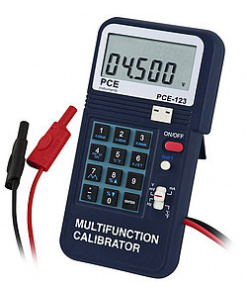
Current Calibrator
PCE-123
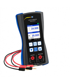
Current Calibrator
PCE-LOC 20
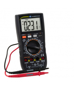
Current Calibrator
PCE-DM 4
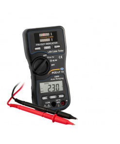
Current Calibrator
PCE-LT 15
Current Calibrator
PCE-LOC 10
Current Calibrator
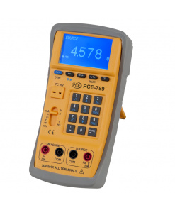
PCE-789
Current Calibrator
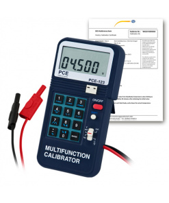
Current Calibrator PCE-123-ICA incl. ISO Calibration Certificate
PCE-123-ICA