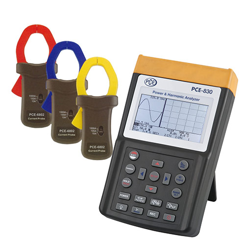
PCE-830-2 Clamp Meter
with 3 phases / Measures power and analyses harmonics / Includes memory, interface, and software
The PCE-830 Clamp Meter is used for measuring one to three phases of electrical quantities for alternating current (AC). This 3-Phase Clamp Meter also measures parameters such as voltage, current, frequency, harmonics, and power as well as indicating, according to standard EN50160, harmonic values, interharmonics, and asymmetrics. Interference, such as interruptions, leaks, overloads, or transience (from 16 µs) are detected with their corresponding values. The backlit LCD, with high resolution, can show up to 35 parameters simultaneously. Up to 3 clips can be attached at the same time to the Clamp Meter. In data logger mode, it can save up to 17,470 readings (3 phases / 4 conductors), in a simpler set up (1 phase / 2 conductors) it can save up to 52,400 readings, split into 85 groups. All this makes the PCE-830 Clamp Meter the ideal instrument for taking measurements over long durations. Measurement values obtained can be sent to a computer and be processed with the included analysis software. The device comes with everything needed to be measuring and analysing from the moment it arrives. Although the Clamp Meter comes calibrated from the manufacturer, an optional laboratory calibration and certificate, that meets ISO standards, can be ordered separately with the device or when a recalibration is required.
– Analysis of a network of 3 phases / 4 conductors, 3 phases / 3 conductors, 1 phase / 2 conductors, 1 phase / 3 conductors
– Measures effective real value (V 123 and I 123)
– Measures active power (W, KW, MW, GW)
– Measures apparent and reactive power (KVA, KVAR)
– Power Factor (PF), phase angle (Φ)
– Measures energy and work (Wh, KWh, KVARh, PFh)
– Measures current from 0.1 mA to 3000 A, allowing for the reserve power of a factory to be determined
– Large LCD that shows up to 35 parameters simultaneously (3P4W [=3 phases/4 conductors])
– CT conditions (1 to 600) and PT (1 to 3000) are programmable
– Indicates current wave forms and voltage overlap.
– 512 KB of memory with programmable intervals to save data every 2 to 3000 seconds, 17,470 readings using the system of 3 phases / 4 conductors
– Indicates wave forms, efficiency parameters, and harmonic distortion
– Backlit LCD with dot matrix
– Average power (AD in W, KW, MW)
– Maximum power (MD in W, KW, MW) with the programmable period
– Analysis of harmonic distortion up to a curvature of 99
– Indication of up to 50º form of harmonic wave
– Indication of the wave form with maximum value (1024 readings / period)
– Analysis of absolute distortion (%THD-F)
– Diagram of graphic equilibrium with parameters of a 3 phase system
– Detects up to 28 transistors (time and cycles) with a programmable threshold (%)
– Relation of 3 phases of voltage or asymmetrical current (VUR)
– Factor of 3 phases of voltage and asymmetrical current (d0%, d2%)
– USB port (optically insulated)
– Integrated timer and calendar to record data
– Maximum diameter of the electrical conductor for the amp clamp: the PCE-6801 ~30 mm / 1.2 in, PCE-6802 ~55 mm / 2.2 in, PCE-3007 ~170 mm / 6.7 in
| Technical Specifications | |
| Measurement values | Measurement ranges / resolution / accuracy |
| PCE-830 + PCE-6801 Watts AC (50 Hz or 60 Hz, PF 0.5 up to 1) | 5.0 W to 999.9 W / 0.1 W / ±1% ±0.8 W 1.000 kW to 9.999 kW / 0.001 kW / ±1% ±8 W 10.00 kW to 99.99 kW / 0.01 kW / ±1% ±80 W 100.0 kW to 999.9 kW / 0.1 kW / ±1% ±0.8 kW 1,000 kW to 9,999 kW / 1 kW / ±1% ±8 kW |
| PCE-830 + PCE-6802 Watts AC (50 Hz or 60 Hz, PF 0.5 up to 1) | 5.0 W to 999.9 W / 0.1 W / ±1% ±0.8 W 1.000 kW to 9.999 kW / 0.001 kW / ±1% ±8 W 10.00 kW to 99.99 kW / 0.01 kW / ±1% ±80 W 100.0 kW to 999.9 kW / 0.1 kW / ±1% ±0.8 kW 1000 kW to 9999 kW / 1 kW / ±1% ±8 kW 0.000 MW to 9.999 MW / 0.001 MW / ±1% ±80 kW |
| PCE-830 + PCE-3007 Watts AC (50 Hz or 60 Hz, PF 0.5 up to 1) | 10.0 W to 999.9 W / 0.1 W / ±1% of measurement range 1.000 kW to 9.999 kW / 0.001 kW / ±1% of measurement range 10.00 kW to 99.99 kW / 0.01 kW / ±1% of measurement range 100.0 kW to 999.9 kW / 0.1 kW / ±1% of measurement range 1,000 kW to 9,999 kW / 1 kW / ±1% of measurement range |
| PCE-830 + PCE-6801 Current AC (50 Hz or 60 Hz, auto range select, TRMS) | 0.04 A to 1 A / 0.001 A / ±0.5% ±0.05 A 0.4 A to 10.0 A / 0.01 A / ±0.5% ±0.05 A 4 A to 100.0 A / 0.1 A / ±1.0% ±0.5 A |
| PCE-830 + PCE-6802 Current AC (50 Hz or 60 Hz, auto range select, TRMS) | 10.00 A / 0.01 A / 4 A to 100.0 A / 0.01 A / ±0.5% ±0.5 A 40 A to 1000.0 A / 0.1 A / ±0.5% ±5 A |
| PCE-830 + PCE-3007 Current AC (50 Hz or 60 Hz, auto range select, TRMS) | 0 to 300 A / 0.1 A / ±1.0% of measurement range 300.0 A to 999.9 A / 0.1 A / ±1.0% of measurement range 1,000 A to 3,000 A / 1 A / ±1.0% of measurement range |
| Voltage AC (50 Hz or 60 Hz, TRMS) | 20.0 V … 500.0 V / 0.1 V / ±0.5 % ±5 digits (grounded) 20.0 V … 600.0 V / 0.1 V / ±0.5 % ±5 digits (phase to phase) |
| Harmonic distortionof AC voltage | 1º to 20º / 0.1% / ±1.0% 21º to 49º / 0.1% / 4% of reading ±2.0% 50º to 99º / 0.1% / 6% of reading ±2.0% |
| PCE-830 + PCE-6801 Harmonics of AC current in % | 1º to 20º / 0.1% / ±0.2% of reading ±1.0% 11º to 20º / 0.1% / ±2% of reading ±1.0% 21º to 50º (A)/ 0.1% / ±5% of reading ±1.0% 21º to 50º (mA)/ 0.1% / ±10% of reading ±1.0% 51º to 99º / 0.1% / ±35% of reading ±1.0% |
| PCE-830 + PCE-6802 Harmonics of AC current in % | 1º to 10º / 0.1% / ±2% 21º to 49º / 0.1% / 4% of reading ±2.0% 50º to 99º / 0.1% / 6% of reading ±2.0% |
| PCE-830 + PCE-3007 Harmonics of AC current in % | 1º to 10º / 0.1% / ±2% 21º to 49º / 0.1% / ±6% 50º to 99º / 0.1% / ±10% |
| PCE-830 + PCE-6801 / PCE-830 + PCE-6802 Power Factor (PF) | 0.00 to 1.00 / 0.01 / ±0.04 |
| PCE-830 + PCE-3007 Power Factor (PF) | 0.000 to 1,000 / 0.001 / ±0.04 |
| PCE-830 + PCE-6801 / PCE-830 + PCE-6802 Phase angle (Phi) | -180° to 180° / 0.1° / ±1° |
| PCE-830 + PCE-3007 Phase angle�(Phi) | 0° to 180° / 0.1° / ±2° |
| PCE-830 + PCE-6801 Total harmonic distortion | 0.0 to 20.0% / 0.1% / ±1% 20.0% to 100% / 0.1% / ±3% of reading ±5% 100% to 999.9% / 0.1% / ±10% of reading ±10% |
| PCE-830 + PCE-6802 Total harmonic distortion | 0.0 to 20.0% / 0.1% / ±2% 20.0% to 100% / 0.1% / ±6% of reading ±1% 100% to 999.9% / 0.1% / ±10% of reading ±1% |
| PCE-830 + PCE-3007 Total harmonic distortion | 0.0 to 20.0% / 0.1% / ±2% 20.0% to 100% / 0.1% / ±6% of reading ±1% 100% to 999.9% / 0.1% / ±10% of reading ±1% |
| Maximum measurement of AC voltage and current | 50 Hz / 19 µS / ±5% ±30 digits 60 Hz / 16 µS / ±5% ±30 digits |
| Peak value measurement of AC voltage and current | 1.00 to 99.99 / 0.01 / ±5% ±30 digits |
| Frequency range in automatic mode | 45 Hz to 65 Hz / 0.1 H z / 0.1 Hz |
| Memory | 512 kB for a maximum 52,420 readings taken by 1 phase / 2 conductors |
| Port | USB |
| Software and cable | included, for Windows 2000, XP, ME |
| Display | backlit LCD with dot matrix |
| Power | 8 AA batteries (Mignon) |
| Dimensions | 257 mm x 155 mm x 57 mm 10.1 in x 6.10 in x 2.24 in |
| Weight | 1.16 kg / 2.56 lbs |
| Operating conditions | max. 85% relative humidity -10º C to 50º C / 14º F to 122º F |
| Type of protection / standards | IEC 61010, 600 V/CAT III |
| Set 1: PCE-830 + PCE-6801 amp clamp (100 A) – Electrical conductor pick-up: 30 mm / 1.2 in diameter – Range selection: manual (1 A, 10 A, 100 A) – Dimensions: 210 mm x 62 mm x 36 mm / 8.2 in x 2.4 in x 1.4 in – Weight: 200 g / 7 oz | |
| Set 2: PCE-830 + PCE-6802 amp clamp (1000 A) – Electrical conductor pick-up: 55 mm / 2.2 in diameter – Range selection: manual (10 A, 100 A, 1,000 A) – Dimensions: 244 mm x 97 mm x 46 mm / 8.6 in x 97 in x 46 in – Weight: 600 g / 1.3 lbs | |
| Set 3: PCE-830 + PCE-3007 flexible amp clamp (3000 A) – Electrical conductor pick-up: 170 mm / 6.69 in diameter – Minimum radial curve : 35 mm / 1.4 in – Length of electrical conductor: 610 mm / 24.0 in – Diameter of electrical conductor: 14 mm / 0.55 in – Dimensions (Box): 130 mm x 80 mm x 43 mm / 5.1 in x 3.1 in x 1.6 in – Weight: 410 g / 14.4 oz | |
| Outline of the PCE-830 | |
| Connecting the amp clamps to the PCE-830: 1. Turn on the device. 2. Push the “1f3f” key until “3P3W” appears on the display for 3 phases / 3 conductors. 3. Connect the 3 test cables from the voltage with L1, L2, L3 and the analyser. The amp clamps are connected, as seen in the image to the right, between the device and the circuit. 4. The results can then be seen on the display. | |
สินค้าที่เกี่ยวข้อง
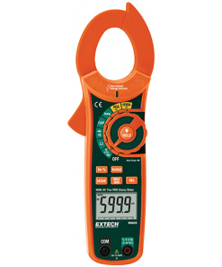
เครื่องวัดไฟฟ้ากระแสสลับแบบ True RMS พร้อมเครื่องตรวจหาแรงดันแบบไม่สัมผัส
แคลมป์มิเตอร์
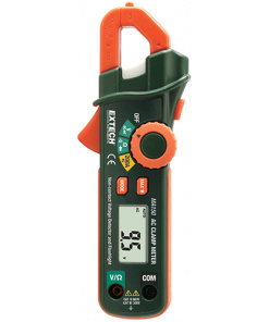
AC แคล้มป์มิเตอร์ ขนาดกระเป๋า เลือกย่านการวัดด้วยตนเอง
MA130 เป็นแคล้มป์มิเตอร์ขนาดเล็ก เหมาะจะใช้วัดในที่แคบสามารถเลือกย่านการวัดกระแสไฟฟ้าด้วยตนเอง 3 ช่อง
เครื่องวัดไฟฟ้ากระแสสลับขนาดเล็ก พร้อมเครื่องมือตรวจหาแรงดันกระแสสลับและไฟฉาย
ความละเอียดสูงมาก (0.1 MA) และมีความแม่นยำสูงเมื่อวัดกระแสไฟฟ้าต่ำ
แคลมป์มิเตอร์
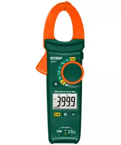
MA443: AC แคล้มป์มิเตอร์ 400A True RMS และเครื่องตรวจสอบแรงดันไฟฟ้าชนิดไม่สัมผัส (NCV)
แคล้มป์มิเตอร์พร้อมเครื่องตรวจสอบแรงดันไฟฟ้าชนิดไม่สัมผัส พร้อมฟังก์ชั่น Type K
แคลมป์มิเตอร์
เส้นผ่าศูนย์กลางปากแคล้มป์ขนาดเล็ก ยาวรีสำหรับที่แคบ
แคลมป์มิเตอร์
แบบ True RMS 1000 A พร้อมอินฟาเรดเทอร์โมมิเตอร์ เครื่องวัดไฟฟ้ากระแสตรงและกระแสสลับหลายฟังก์ชั่นพร้อมอินฟราเรดเทอร์โมมิเตอร์แบบไม่สัมผัส
฿12,119.89 incl VAT

